Overview
- Connectivity of charging device to different contact systems
- Distribution of electrical output among the charging points
- High-capacity charging device
Connectivity of charging device to different contact systems
In order to achieve a high degree of independence from manufacturers, three different system adaptions are planned for three different contact systems.
- ACD-U adaption
Energy transmission is realized identically to the CCS system via contacts for DC+ and DC- that are fed directly by the charging device. In addition, the PE potential is passed on to the vehicle to detect insulation defects. To detect interruptions in the energy transmission process, a specific CP contact is employed. Interruptions within the DC wires that are strung together with the CP wire will lead to the immediate termination of DC energy supply by the charging device. This means that the occurrence of light arcs in case of a malfunction is prevented.
In the ACD-U adaption, communication between vehicles and charger is wireless according to the OppCahrge protocol and the ISO15118-8 standard. - CCS plug adaption
The CCS plug is also fed directly with DC+ and DC- from the charger, and the PE connection is used. The CP contact is monitored during the charging process in order to detect any interruptions.
In contrast to the ACD-U adaption, however, the communication is carried out via PLC using the CP contact according to ISO 15118-3. - MCS plug adaption
The MCS plug adaption is similar to the CCS plug adaption. However, in this case, it is planned that the communication will be realized via an additional contact pair carrying a differential signal. This way, potential problems that may arise from relying on the PE wire, as in the CCS plug adaption, can be prevented.
Within the project, the first two contact system adaptions will be realized and tested. Contacting via the MCS plug adaption is under development.
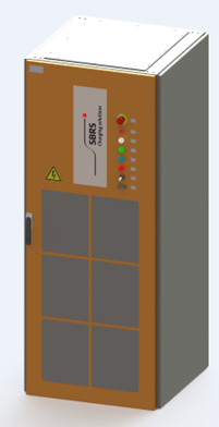
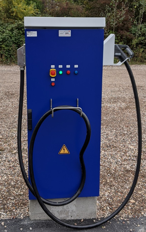
The system will be provided in the shape of a wall box containing all necessary communication interfaces. This wall box is equipped with a fixed CCS cable and contains the required modems and the ACD-U control unit. The wall box communicates with the charging device via CAN-Bus, which allows for larger, safe distances between the power electronics and the contact point.
Distribution of electrical output among the charging points
If we observe the typical day-to-day operations of a logistics yard, it becomes obvious that only short stops are scheduled at cargo delivery stations. For this reason, the charging process at that location should be carried out at maximum capacity. Due to the large number of delivery stations, it would be uneconomical to equip every charging point with its own high-capacity charging device. It is therefore advisable to install fewer chargers and supply the charging points in a needs-based way with the required power.
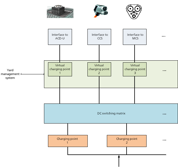
From the point of view of the vehicles, however, all charging points must be signaled as ready because the power can potentially be extracted at any of the charging points. This is reflected in the term “virtual charging points”.
Within the scope of the project, the implementation of virtual charging points is tested. For this, all charging points are equipped with a comprehensive communication interface that communicates with the vehicle and with the yard management system, so that it can give the signal that the charging points are ready to connect. When vehicles arrive, the real capacity of the connected power suppliers will be distributed among the charging points currently in use with the help of a DC distribution matrix.
High-capacity charging device
In order to reach the required charging capacity, it is planned to connect several chargers in parallel.
This parallel circuit requires synchronization of the individual chargers, so that undesired balancing processes are prevented. The technology required for this synchronization will also be developed within the project.